
Photographic accessories such as L-brackets and pan heads are covered. Detailed plans are given on how to create custom L-brackets from basic tools and supplies, to the creation of a pan head made from a compass and a bubble level.
- Camera L-Brackets
- Camera Mount Knob
- Monopod
- Monopod Panhead
- Demarcation Plates
- Underwater Tripod Leg Weights
- Canon PowerShot 600 External Power Supply
-
- For a detailed description on the use of a monopod with QTVR, ckeck out:
- www.OutsideTheLines.com/qtvrmonopod
Camera L-bracket
In order to get your camera sitting with a high field of view , you need to orient your camera in a vertical fashion. To do this you need an L-bracket, easily made from aluminum flat bar and stainless steel nuts & bolts. In addition, we like to use a tripod/camera quick release plate for our brackets to make it simple to change rigs. In particular, we use a Bogen (Manfrotto) hex quick release plate for all of our brackets due to its strength and durability.
The use of aluminum is recommended over steel or wood because it is soft, light and strong. Aluminum is very easy to work with - it is east to cut, bend, file, and drill. You do not need a machine shop to work with it and it is inexpensive and readily available. Generally you will want to work with anodized aluminum flat bar that is 1/4" x 1 1/2". The 1/8" thick variety is too thin and will bend with a camera attached, while the 1/4" thick stock is rigid enough for the heavier cameras you may want to use. The 1/4" x 1 1/2" stock can be found at most good hardware/building supply stores for approximately $4.00 USD per foot; you should need no more than 2 feet to make a working bracket. In addition to the aluminum flat bar, you should use stainless steel mounting hardware to bolt your L-bracket together. By using the aluminum flat bar and stainless mounting hardware, you will end up with a piece of camera equipment that will last a very long time due to its strength and corrosion resistance.
To build a basic camera L-bracket, you will start with placing a nice tight 90 degree bend in the 2 foot aluminum flat bar 8 inches from one end. To do this, clamp down the short end in a strong vise, putting the 8 inch mark just above the clamp. With the remaining 16 inches above, pull the flat bar down, putting a nice tight 90 bend in the metal. You may need to get physical with a hammer to get the bend nice and flat. Congratulations, you now have a large bent piece of metal. At this point, using a hacksaw with a metal cutting blade, cut off 8 inches from the long end. You should now have one 8 inch flat section and one 16 inch section bent in half.
Take the 8 inch section, drill a couple of holes at its end, and on the quick release plate, and bolt the two together as shown. The quick release plate may need only one additional hole drilled as there is generally a center hole already in place.
Next, take the bent section and drill a camera mounting hole at some point along the vertical side (pick one). Now the fun part, well, the hard part actually. The time has come to bolt together the bent section to the flat section (with the quickrelease attached). First, note that the center of the quick release plate will be the center of rotaion and thus the point at which the lens nodal point must be centered. With the camera attached to the bent section, hold the two parts together at whatever weird angle is needed to get the lens nodal point sitting over the center of rotation. Be sure to determine the nodal point center with the wide angle lens, or wide angle adapter, attached to the camera. Once you have done this, drill the appropriate holes in the two parts and bolt them together, producing a finished L-bracket. Excess metal should be cut away and the bracket should be filed to remove the rough edges from all the cutting, drilling, and banging, thus producing a semiprofessional part that will last a lifetime.
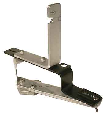
We have built three different brackets for different uses. The largest bracket was built for underwater use and was designed around a standard underwater camera mounting plate (the black plate in the photograph) with a strobe attachment point. Due to the weight of the camera and strobe, we had to build a reinforced structure for the entire unit to sit upon. The base is made up of 1/4" aluminum plate with a 1/8" plate riser to hold the camera mounting plate steady over the quick release plate.
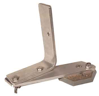
In addition to the underwater bracket, we built a generic bracket which we use for a Nikonos V above water with its 35mm lens, an Olympus OM series 35MM camera with its 28mm lens, and a Canon RC-250 video still camera with its wide angle lens. The lens nodal point was matched to that of the underwater bracket and works well for all the above mentioned cameras. This bracket is much smaller and lighter than the underwater bracket and so is used for both a tripod and a monopod for normal duty shoots. For above water shoots with a strobe, we use the underwater bracket due to its strobe clamp and sturdiness.
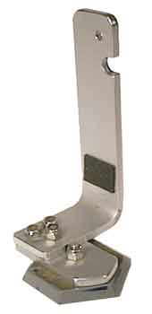
The L-bracket for the Canon PowerShot 600 was the next bracket to be made, and is simply another example of the generic bracket. The important change from the generic bracket, other than nodal point location, is the slot cut out of the bracket for an external camera power supply plug. We have also placed a rubber strip at the base of the bracket for the camera to sit against when it is attached to help keep it sitting firmly against the plate.
Camera Mount
Knob
The camera mount knob is used to attach the camera to the L-bracket. The US thread standard for camera mounts is 1/4"-20, so it is a simple matter of building your own mounting knob.
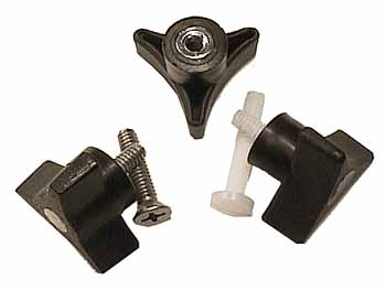
For cameras with plastic mounting threads, we use a nylon 1/4-20 bolt to attach the camera to the L-bracket. The theory being that the nylon bolt will strip before the plastic threads on the camera do. For underwater use, we use stainless bolts to attach the Nikonos V to its bracket since the Nikonos has metal mounting threads. The basic construction is very strait forward. The following parts are used to construct a camera mounting knob:
- Three prong 1/4-20 female threaded insert clamping knob
- Nylon or stainless 1/4-20 machine screws
- Epoxy to seal the unit
Thread the bolt into the clamping knob until the correct amount of thread is exposed. You can determine the correct amount of thread by checking your camera and determining how deep the mounting threads are. We have found that when you use 1/4 inch aluminum flat bar for your L-bracket, the amount of exposed thread is about 1/2 inch. Cut the bolt so that the other end of the bolt sits within the body of the clamping knob and epoxy the entire thing shut. The epoxy will keep the bolt from moving and turning within the knob, thus providing a solid mounting bolt for your camera and L-bracket.
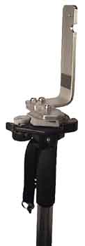
Monopod
There is really nothing to make here - just things to put together. After running around with a tripod for a year, we decided to give it up (for the most part) and use a monopod. Monopods are smaller, lighter, less intrusive, and easier to set up. The monopod we found was a Bogen #3006 with a cost of about $40 USD new. We purchased a Bogen quickrelease head for around $18 USD and we were in business. With this setup, we can use all of our existing mounting brackets due to our prolific use of hex quick release plates.
Monopod
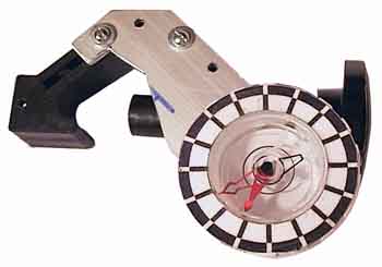
Panhead...the use of Earthly mechanics
The problem with a monopod is the inability to keep the pod precisely level and get consistent image overlap as you can do with a tripod and panhead. To solve this problem, we make use a the gravity and magnetic field of the Earth. We have designed a unit that attaches to the side of the pod's leg and gives you all the important rotation and level information at a glance. Using a bubble level, you can be sure the pod is level at all times. Using a compass with custom demarcations you can point the needle to the appropriate spot for consistent image overlap. No metal parts can be used as they can affect the compass readings.
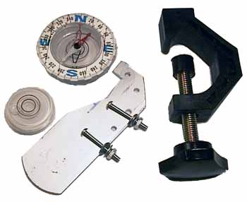
We started with the following parts:
- Photographic light stand accessory clamp reduced to the clamp only. This clamp should be made of plastic or aluminum only since any metal will affect the compass readings. Plastic is preferred as it can be easily drilled. This clamp is the carrier for the rest of the panhead gear.
- A strip of 1/8" x 1 1/2" anodized aluminum flat bar approximately 6" long.
- A large carpenters bubble level used to level the monopod.
- A large, good quality mountaineering compass. The compass must be large to help prevent needle bounce and should be of good quality so that the needle will move freely. It is best for the body of the compass to be made of clear plastic with a wide outer rim for the degree marker. With a compass made of clear plastic, it is possible to glue the bubble level below the compass so that you can see both indicators at the same time, allowing you to accurately position both the compass needle and bubble level with ease. The wide, easy to read, degree marker on the outer rim of the compass will be replaced with a custom demarcation plate for the number of images needed for a full panorama.
With all of these parts, you first cut the aluminum bar to fit on the accessory clamp as a holding plate, making sure the unit can still be attached to the monopod. The end of the aluminum plate should stick out about 4" from the side of the monopod so that you can read the indicators which will sit on the end. Once the plate is cut to shape, holes must be drilled in both the plate and clamp and the two attached together with small bolts. Now that you have a plate on which to place the compass and bubble level, it is time to adjust the levelness of the plate relative to the monopod itself. For this you will need two bubble levels. The first will sit atop the monopod on the quickrelease head. This level is the reference level and will be used to calibrate the aluminum plate. The second bubble level will sit on the end of the aluminum plate. With the clamp attached to the monopod, you will need to bend and twist the aluminum plate until it is level with regard to the top of the monopod head. For this reason, you should use the 1/8" x 1 1/2" aluminum flat bar since it is easy to bend and twist for any adjustments you will need to make for an accurate level. From here it is easy - you simply glue the compass on top of the bubble level and place that unit at the end of the aluminum plate. With your custom degree marker in place, you are ready to shoot panoramas with a monopod, and you can always start your panoramas by shooting north, since you have a compass to tell you where that is. Placement of the monopod panhead should be several inches below the quickrelease head for ease of reading the indicators and working the camera. We have found that is is easy to use if you are looking down on the unit to see both the compass needle and the bubble level. This places the unit near the bottom of the first extension section of a three section monopod.
Demarcation
Plates
The following actual size demarcation images were created using Adobe Illustrator. The smaller marker plate is custom sized to replace the standard Bogen panhead degree plate and is given a magnetic backing (available at most photographic stores for use with photographs). We glued a large metal washer to the Bogen panhead upon which we place our custom degree markers, which works well above and below water. The larger marker plate was created to be cut into a ring and glued to the outer edge of the compass used for the monopod panhead.
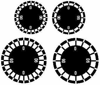
Both markers have been created with 24 and 16 indents, with the 16 mark disk the most versatile. Our choice of 16 marks gives us 55% overlap on a Canon PowerShot 600 with its wide lens attached. The Canon RC-250 video still camera can store 50 images per floppy disk so we can get 3 panoramas (48 images) per floppy with its wide angle lens with about 33% image overlap. In addition, we can get 2 panoramas (32 images) from a roll of 36 exposure film, with a few extra exposures for mess ups and emergencies.
To get 12 shots per panorama, you would use the 24 indent marker and shoot every other mark. We have found that 12 images is too few for 35mm cameras with a 28mm lens since there is not enough image overlap to account for exposure latitude. We have also found that 12 exposures is not enough for a Nikonos V with a 20mm lens due to the lack of strobe flash angle, even with a wide angle strobe. 24 shots per panorama will get you 1 panorama on a 24 exposure roll of film and is good for standard 35mm lenses and pretty much gives you greater than 50% overlap with most cameras with wide angle lenses.
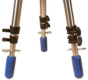
Underwater
Tripod Leg Weights
The following photograph is a good indication of how these leg weights were made:
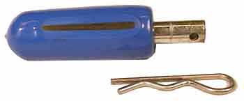
The component parts that make up the leg weights are:
- 2 lb. diving belt bullet weight
- Aluminum bar for tripod leg insert
- Hitch pin to keep the weight attached to the tripod leg
- Small cotter pin to keep the aluminum bar attached to the diving weight
- Epoxy to fill the weight which prevents internal corrosion, keeps the leg pin tightly attached, and adds to the fit & finish of the completed part.
First start by drilling a hole in the weight deep enough so that you can insert the aluminum bar into the weight and see it through the belt slot in the weight. Next cut a piece of aluminum round bar about 3 to 4 inches long. Drill a hole at one end large enough for the hitch pin to be inserted. In the other end drill a smaller hold into which a small cotter pin can be inserted. Insert the aluminum bar into the dive weight and slide the cotter pin into the aluminum bar through the belt slot in the weight. The belt slot in the dive weight can now be filled with epoxy to seal it closed. While the epoxy is drying, you can drill a hole in the tripod leg large enough for the hitch pin to be inserted. One this is all completed, you simply insert the leg weight into the tripod leg, and fix it in position with the hitch pin. You have now added 6 pounds to your already heavy tripod.
Canon
PowerShot 600 External Power Supply
The Canon PowerShot 600 has a power input port on the body of the camera which requires 10.5v of regulated power. By adding external power to the camera, you can use a large hard drive and take thousands of pictures without having to recharge the batteries. The idea to get this power is a simple one. You need a device that can eat 12v and spit out 10.5 volts of regulated power. You can buy devices that take 12v and spit out 9v, 6v, and 3v, but not 10.5 volts. To solve this problem, you merely take your 12v DC to DC regulated adapter, change a few internal resisters, and you now have 10.5 volts of regulated power rather than the other voltages you used to get.
For those of you adept at basic electronics, the procedure is quite trivial. Start with a RadioShack part number 270-1562E High Current DC-DC Adapter. This adapter allows you to switch between 12, 9, 6, and 3 volts. Internal to this unit are five resistors and a standard LM317 voltage regulator part. By simply changing three of the resistors to new values, you can get the unit to deliver 10.5 volts of regulated power, though you should cut some internal traces to prevent other voltages from showing up. The new resister values should be (the resister numbers are marked on the circuit board) R1=270 ohm, R2=1k ohm, R3=1k ohm. R2 and R3 are wired internally in series at the 6v setting providing 2k ohm. The LM317 voltage regulator equation is Vout = 1.25v * (1 + (R2 + R3) / R1) = 1.25v * (1 + (1000 + 1000) / 270) = 10.5v. With this setup, the 6V setting will now deliver 10.5 volts. Note that you could also have simply replaced R2 with a 2k ohm resister to have 10.5 volts delivered at the 3V switch setting. You should be sure to disable the possibility of delivering anything other than 10.5 volts since the PowerShot 600 has a fairly high price tag. Using a volt meter, make sure you only get 10.5 volts from any of the switch settings.
For our unit, we rewired the switch and circuit board such that three of the settings are <OFF> and one is <ON>. When the single <ON> setting is switched, the LED is enabled and 10.5 volts is sent to the output. We made the following modifications:
- Cut the trace going from positive power input to the LM317 input voltage point. This is done since the switch will eventually be used to power on the unit.
- Cut the trace going from positive power input to the positive side of the LED. The LED will eventually be powered by the output voltage.
- Cut the common 3/6/9 volt trace at the switch killing the old reference resistance
- Cut the 3 volt trace at the switch killing the 3 volt setting
- Cut the 6 volt trace at the switch killing the 6 volt setting
- Cut the 12 volt trace at the switch killing the 12 volt setting
- Removed resister R4 thereby killing the 9 volt setting
- Changed resister R1 to 270 ohm
- Changed resisters R2 and R3 to 1K ohm each
- Added a wire from the output voltage of the LM317 to the positive side of the LED. The LED is now powered when the unit delivers output power
- Added a wire from the 12 volt switch setting to the LM317 input voltage point. We now provide power to the unit when the switch is set to the 12V setting.
- Added a wire from the LM317 ADJ point to the end of resister R3 (not between R3 & R2). This provides the adjustment resistance needed to get 10.5V output.
The LM317 voltage regulator requires a heat sink, so if you plan on making your own unit, be sure to give it lots of heat sink breathing room to cool off. The RadioShack unit is well ventilated and works great when converted.
Now that you have your power converter, you need to supply it with an input voltage of at least 12v. We have found the easiest thing to do is wire up two 6v camcorder batteries in series to get 12v. We then send this power into the regulator unit and we have power. We found a cheap camcorder battery belt which allowed us to rewire the three independent batteries into a single power source providing 12v or 18v depending on the number of batteries we have in the belt.
So, great, now you have power into the newly modified regulator, and a wire coming out with 10.5v. You now need the correct plug to stick this power source into your camera. There are some accessory tips that come with the DC-DC adapter, one of which is bound to fit in the PowerShot 600. When you find the one that fits, be sure the polarity is set correctly or you will have just blown up $1000 USD and have a smoking shell of a camera. Once you determine the correct tip polarity, you should find a way to glue the tip in place to prevent an accidental polarity change and blowing up your camera. Be sure to test the voltage coming from the tip - be sure it is 10.5v with the correct polarity. Check again. Be paranoid. For our use, we had an extra Apple Newton wall power adapter, which just happens to have the correct size plug.

Home - www.OutsideTheLines.com
Questions or comments about this site should be directed to:
SiteGuy@OutsideTheLines.com